Overview
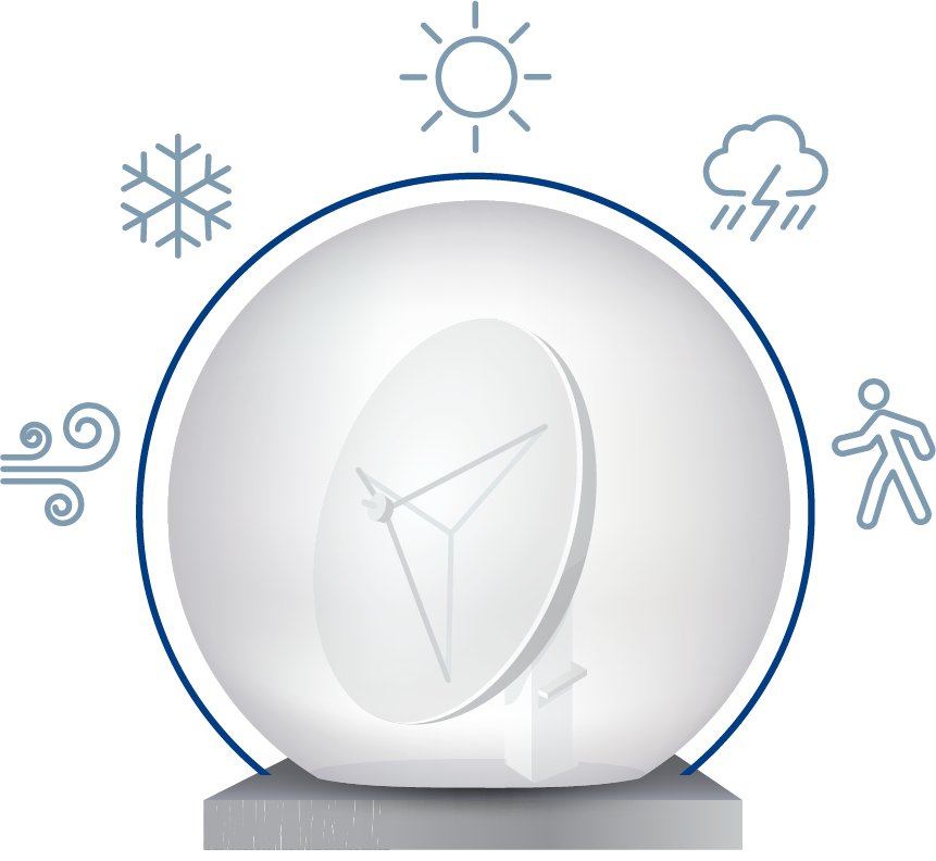
The basic function of a radome is to provide a defense between an antenna and the outside environment while simultaneously minimizing impact on electromagnetic performance. Radomes protect a wide range of ground and maritime systems for communications, weather radar, military precision tracking, fire control and other antenna systems. The proper selection of a radome can improve overall system performance, reduce downtime, and extend the antenna’s useful service life through prolonged component operation and possibly reduce antenna maintenance costs.
Adding a properly designed radome can be a huge benefit to an antenna system faced with adverse weather conditions. A radome will reduce lifecycle maintenance costs and allow for better antenna uptime during significant weather events.
We offer radome solutions capable of operating in common Air Traffic Management bands. The transmission loss prediction below is a sample of one solution developed for a specific ATM application with operating frequencies from 1-4 GHz. The transmission loss prediction takes into account radome diameter, dish diameter, as well as the ATM radome panel construction, both for the body and bolting seam.
Save Your Antenna
An antenna exposed to high winds, snow, ice, humidity, UV radiation, salt-laden air and other harsh environmental conditions results in reduced system up-time, component degradation, accelerated corrosion, projectile impacts, and reduced overall system performance. A radome isolates the antenna from these conditions, allowing operations to continue with much less downtime than experienced on a system without a radome.
The structural capability of a radome provides shelter for personnel performing operational duties and maintenance activities, and a security screen by preventing visual observation of the antenna system.
Isolate Environment
Increase Security
Reduce Downtime
Improve Antenna Performance
Reduce Lifetime Maintenance
Shelter for Operators
Why Infinite RCS
Our expertise stems from key personnel with years of experience analyzing existing radome systems, creating innovative design solutions, and developing a system for replacement of aging radome installations worldwide.
The extensive maintenance and repairs required on older radomes often result in downtime, reduced performance, and substantial maintenance and panel replacement costs for asset owners. IT RCS has developed viable and affordable solutions for radome fleet replacement. The radomes we manufacture are designed for a minimum service life of 20 years with a reduction in lifecycle costs up to 50%. These savings are realized without degrading performance; in fact, our products have shown substantial RF and structural performance improvements over many aging radome systems
Worldwide Provider
Experienced Professionals
Innovative Designs
Top Product Value
Key Product Information
Years of experience supplying radomes provides the IT RCS team insight few others have. We have experience with specific elements of antenna design and operation which are critical to proper radome design. That allows us to design for better performance of the antenna housed within the radome.
Composite Radome Features
- Tuned Bolting flanges
- Compatible with Dual Pole Antenna Systems
- Low IFR
- Pseudo-Random Panel Geometry
- Non-Coherent Scattering
- Improved Sidelobe Performance
- Antenna Polarization Neutral
- Low Passive Inter-Modulation (PIM)
- Durable, Long-Lasting Materials
- Optimized Panel Sizes for Installation and Transport
- No Metal Framework, Rigid, Self-supporting
- Operational without Power
Environmental
Materials
RF Performance
- Tuned Bolting flanges
- Compatible with Dual Pole Antenna Systems
- Low IFR
- Pseudo-Random Panel Geometry
- Non-Coherent Scattering
- Improved Sidelobe Performance
- Antenna Polarization Neutral
- Low Passive Inter-Modulation (PIM)
- Durable, Long-Lasting Materials
- Optimized Panel Sizes for Installation and Transport
- No Metal Framework, Rigid, Self-supporting
- Operational without Power
Panel Geometry
A pseudo-randomized panel layout is used for most configurations. Panel-to-panel joint attachment is accomplished through an impedance matched bolted lapjoint improving overall radome performance by minimizing the effets of insertion loss and cohert scattering.
Export Restrictions
Most of our radomes are classified as EAR99 or no license required (NLR), and do not require UTAR control. IT RCS does not conduct business with entities who are not in good standing with the U.S. Government.
Shipping
Each radome is packaged in fully enclosed wooden shipping crates compliant with international shipping standards to protect the contents form damage during transportation. Most crates are sized to fit inside a standard shipping container. Optional air transport crating is possible for most radome models.
Radome Warranty & Service Life
We have confidence in the durability of our radome products. We offer a warranty against defects in workmanship for 24 months from the date of installation or 30 months from the date of delivery—whichever comes first.
The nominal service life for our randomes is 20 years. With minimal maintenance and cleaning, the service life should exceed 20 years.
Model Identification Terrestrial
Testing & Certification
We perform internal testing and material evaluation for the development of our radome materials and designs. For structural testing and material properties certifications, we utilize the services of accredited testing laboratories.
Mechanical and Environmental Considerations
Standard Configuration
Our radomes are evaluated to ensurethey meet each customer’s specific requirements. As such, we have a wide range of radome models available with high wind speed ratings, greater snow and ice load capabilities, or the ability to meet other atypical environmental conditions. All configurations remain compliant with our self-imposed structural safety factors.
Physical Considerations
Size Variables
Mounting Configuration – Ground or Elevated
Basic Wind Speed and Directionality
Gust Effect Factors
Weather Factors – Hurricane and Non-hurricane Locations
Terrain Exposure – Vegetation
Topographic Factors – Mountains and Gorges
Snow/Ice Loading
Balanced Loading
Unbalanced Loading
Exposure Factor
Thermal Factor
Importance Factor
Radome Diameter
Mounting Options
Radome Diameter
Truncation is the height of the radome from base to zenith expressed as a percentage of the outside diameter. Truncations up to ~90% are available. Selection of the correct truncation is critical to achieving optimum RF performance. Ideally, the center of the radome and the rotation center of the antenna should be collocated. This arrangement ensures the antenna is always looking through the radome wall uniformly on either side of the antenna phase center projection, minimizing the impact on key performance characteristics.
Sizing
Radome diameter and truncation are primarily driven by antenna size and type. Most IT RCS radomes have a spherical shape with a trunca-tion or height usually between 70% and 90% of the radome diameter.
Although the exact radome size is determined by the specific antenna, some basic assumptions can be made to aid in obtaining a rough radome size. For preliminary design estimates, the following assumptions are used.